
Series and Parallel Connections - Part 2
Introduction
We’ve now talked about the theoretical advantages of series and parallel connections. Want higher voltage? Go series. Want the same voltage with extra capacity or plug-and-play options? Go parallel. But there are real-world consequences to each connection type that we must be aware of for DIY or professional installation. Let’s look at how each type of component behaves in series versus parallel, starting with our basic loads.
Need to brush up on the fundamentals? Check out the previous article for the basics!
Loads in Parallel
Loads in parallel are really the only way to go. Whatever system voltage you’re working with is the voltage your load gets when its plugged into a socket. If you need a different voltage - use a converter and sockets rated for the new voltage. USB sockets (not the cords) have these converters built-in! That’s why you get 5V out of a USB socket that is plugged into a 12V cigarette plug, for example.
Limitations and Real-World Considerations:
There are factors that limit just how many devices we can plug in to sockets all at once. The main limit is current rating of our wires and fuses. A wire can only handle so much current before it heats up and eventually melts. Melting wires are dangerous because they can cause fires, which is why there exist wire ampacity tables so that we can size our wires safely. Sizing wires is a different subject for another article, but just remember this: Size your wires conservatively, and use fuses rated for 125% of your wire’s current rating! This will make sure your circuit is protected in case you plug in too many things at once.
Another factor is wire length. In the real world, wires are not perfect conductors. They have their own properties which resist the flow of current, although they do this much less than other materials. This causes what is called a voltage drop, or a decrease in voltage from one end to the other. This voltage drop causes the wire to heat up depending on how much current is pushed through it. Longer wires have more resistance, which causes more voltage drop and heat. Thicker wires have less resistance, so we can combat the effects of length by upsizing our wires.
So how does wire length actually affect parallel connections? Since there is a voltage drop, the voltage on the far end away from the battery will be lower. More current pushed through a thin wire will cause a greater voltage drop. So if we plug in a bunch of devices on the other end of a long wire, those devices will see less and less voltage. Eventually there comes a point where the loads cannot even turn on because voltage is just too low.
This is why, for example, Starlink mini cannot be powered directly off of 12V with the 50ft cable they give you. Even though the dish is able to handle 12V, the voltage drop across that 50ft wire is so high that the voltage the dish actually sees is around 11 or even 10V - too low for it to function. The solution? Use a shorter or thicker cable than what they provide, or just use a 24V source!
Loads in Series
We’ve already touched on this, but for the most part, loads are never connected in series. There are a few exceptions like old-school Christmas tree lights, string lights and similar. But because of their impracticality and ‘if one fails, all fail’ logic, they’ve been largely phased out with parallel technology.
Batteries in Parallel
Connecting batteries in parallel is great because it gives us extra capacity and more current output without changing the system voltage. Maybe you need more energy for those stormy weeks. Or perhaps you need to provide a load with more current than a single battery can provide. A solution is to add more batteries in parallel.
Combining batteries in parallel is like doubling the size of a water reservoir. You can store twice the amount of water, and you can send more water in or out without harming the local ecosystem (in theory). Just make sure you increase the size of the spillway (wire) so that it can handle the extra flow of current!
Limitations and Real-World Considerations:
In theory, wiring batteries in parallel should be as easy as using wire to connect each of the positives together, and likewise for the negatives. However, this only works in theory because theoretical wires have no resistance. In reality, all wires have resistance, and even small imbalances can cause big current sharing issues. One of the most common mistakes is to connect multiple batteries in a line, similar to what is shown below.
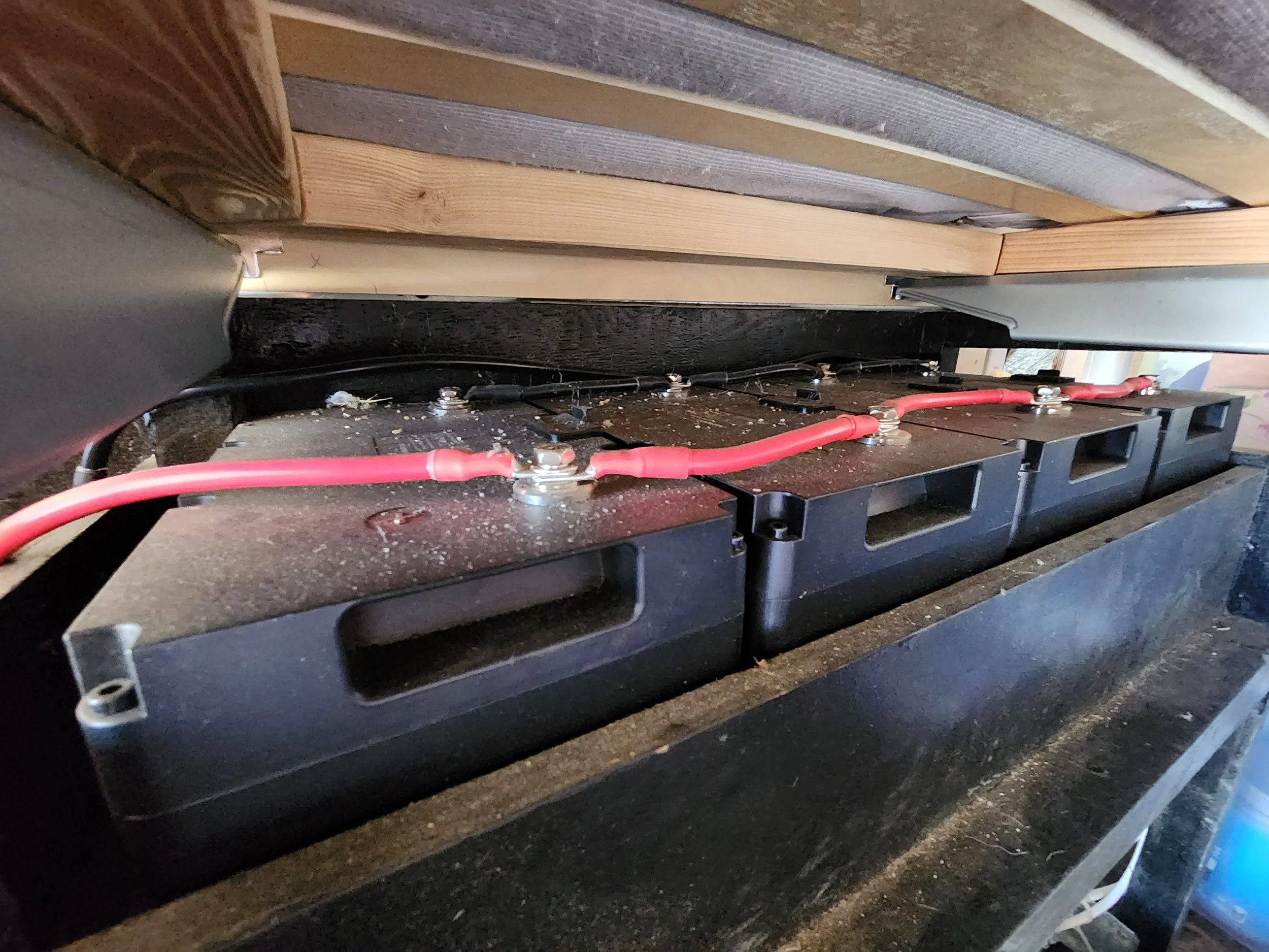
Figure 5: An unbalanced parallel battery bank connection. The battery closest to the electrical system will die before the others. In this setup, the black and red wires are tapped from opposite ends of the battery bank. This helps but does not perfectly balance the batteries, as the outer two batteries will die prematurely.
In this case, the black wire is tied to the right-most battery and the red to the left-most. But let’s consider what would happen if both wires were tied to the left-most battery. Because that battery has the least amount of wire between it and the system, it will provide the most current. The small resistance connecting that battery to the next one would reduce the amount of current the second one could provide. This pattern would repeat until the final battery, which would discharge the slowest. This current imbalance will cause the first battery to die prematurely, wasting money as the batteries are not shared equally.
The best way to fix this issue for 3+ batteries in parallel is to use a set of battery ‘bus bars’. Bus bars are just solid tinned copper with low resistance connection points. These allow us to connect 3-5 batteries together with as little resistance as possible. This is ideal for two reasons. First, we don’t have to use massive wire like 4/0 cable for every single battery connection. We can instead send 4/0 from the bus bar to our 3000W inverter, for example, and just use 4AWG wire to feed each battery individually. While we might draw 250A from the 3000W inverter, each battery would only send out ¼ of that, or about 65A. If for example we only had 3 batteries, that would be 250 divided by 3 or ~85A, so we’d need 2AWG wire for each battery.
We should make sure that the individual battery wires are about the same length + / - an inch. If the wires aren’t equal length, current will not be shared equally. And as another nuance, the positive and negative wires do not have to be the exact same length. They just have to be consistent per each battery. So if one battery needs a 4 inch black wire and an 8 inch red wire, do likewise for all 4 batteries and you’ll be golden.
The second reason bus bars are ideal is for isolation and maintenance purposes. Let’s say one of the batteries fails, but the other 3 don’t. With a bus bar system, we can disconnect just the faulty battery and swap it out with a fresh one without ever disrupting the power to our system. Compare that to the system of Figure 5. If one of the middle batteries failed in that configuration, we’d have to disconnect nearly all of the batteries just to swap out the one!
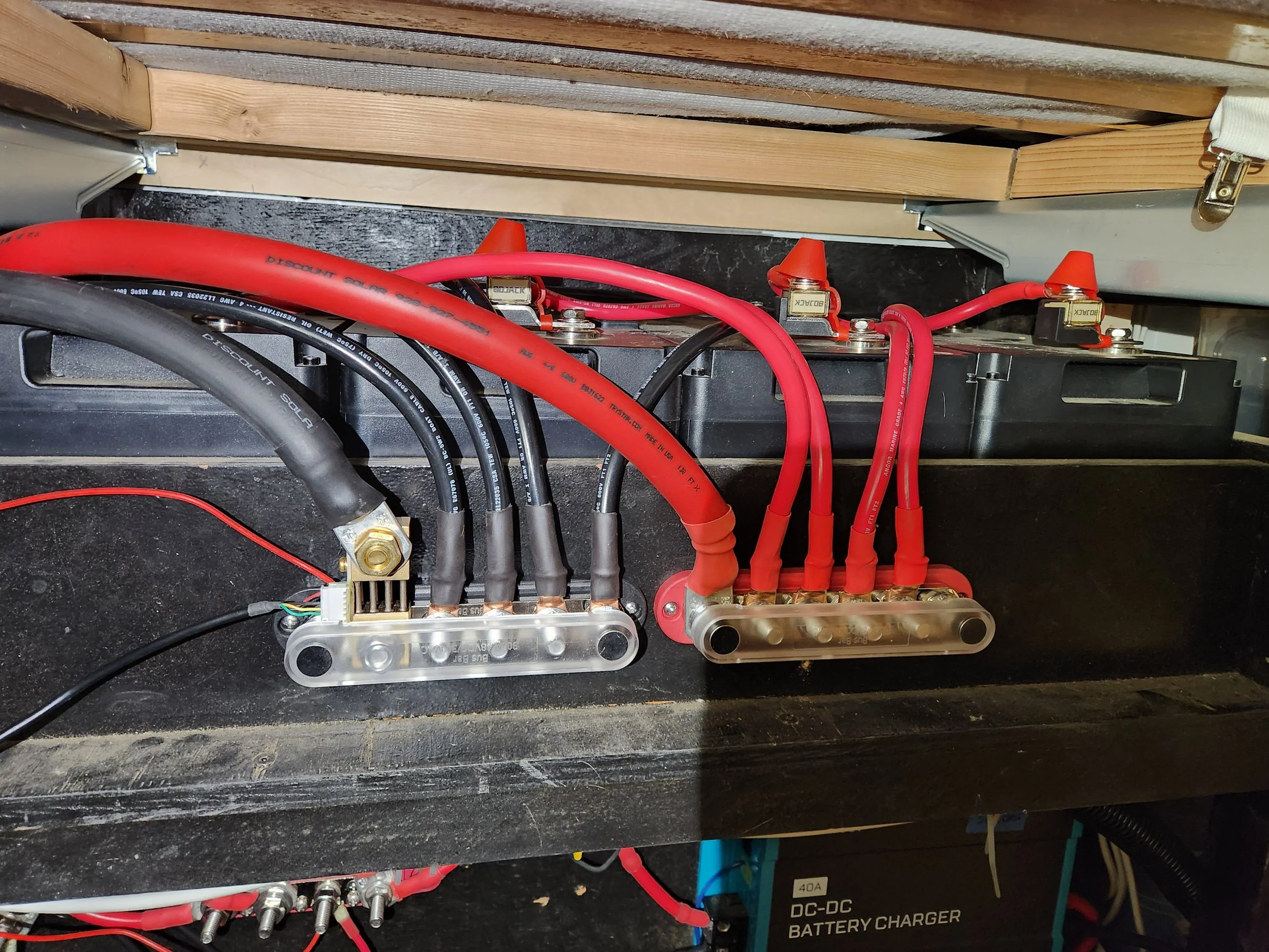
Figure 6: A battery bank connected with bus bars for optimal current-sharing.
There is another way to perfectly balance batteries in parallel without using bus bars, but it only works for 2-battery systems. Its similar to Figure 5, except it only is valid for two batteries. That is to tap the output wire on the negative terminal of one battery, and the positive terminal of the other. In other words, each battery should have a total of 3 wire lugs connected to its terminals, instead of having 4 lugs on one battery and 2 on the other.
With this connection, the wires connecting the two batteries only needs to be rated for half of the maximum system ampacity, while the output wire must be full-sized. This connection requires the smaller red and black wires to be the same length + / - one inch, as otherwise it will cause an imbalance in how current is drawn.
If we were to add more batteries in between like in Figure 5, the middle batteries would see more resistance and hence would not be able to share as much current as the outer batteries.
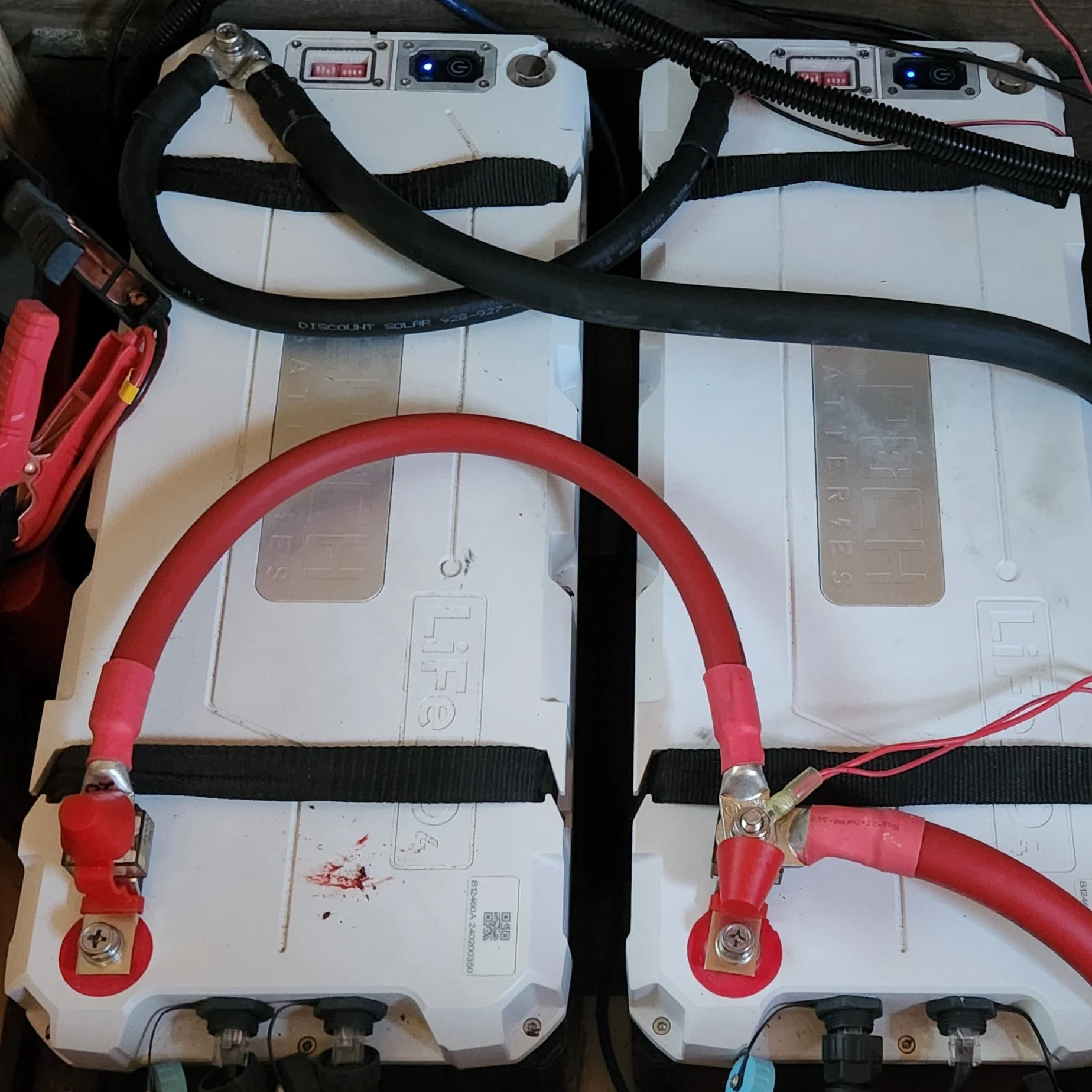
Figure 7: A dual-battery balanced parallel connection without bus bars. Note that each battery has a total of 3 lugs connected to its terminals.
Aside from wiring, there are internal battery limitations that prevent us from connecting as many batteries in parallel as we might like. Each battery has its own internal resistance, usually <10 milliohms for LFP batteries. This resistance often varies between batteries, and it can depend on manufacturing tolerance limits, age, and other imperfections. The batteries have a Battery Management System (BMS) built in which helps balance out these imperfections, but this alone is not always enough.
Battery manufacturers often limit battery connections to 4S4P, or four in series and four in parallel. This is mostly a risk-prevention tactic and not a set-in-stone limit, as you might be able to connect more than four in parallel without issue. But you just won’t get optimal performance and there is an increased risk of premature failure or even thermal runaway if one of the batteries finds itself abused from mismatched current sharing.
This same logic is why you shouldn’t connect batteries that are more than a few months apart from each other in age. As the batteries deteriorate, their internal resistance increases. Add two batteries of different internal resistance in parallel, and you might find one contributing 10-30A less than the other given a 100A total load. I am actually guilty of this sin, as I bought my 3 batteries at different times within the first 1.5 years of owning my travel trailer. But because I didn’t use my system so heavily in that first period, and because I bought the same exact model of battery from the same exact company and used a battery bus bar system, I have not had noticeable issues (yet - fingers crossed!). It has been roughly 2.5 years now since I bought my first LFP battery.
Battery imbalance issues can also occur when mixing batteries from different manufacturers. A 100Ah Epoch battery will likely not have the same internal resistance as a 100Ah LiTime battery. Overall, pick your manufacturer wisely, figure out how many batteries you need, buy them all at once, and combine them properly with bus bars and right-sized wire of equal lengths. It sounds like a lot of effort but it’s the difference between batteries that last 3 years and 10 years.
Batteries in Series
The biggest downside to connecting batteries in parallel is wire size. Typically, the more batteries we put in parallel, the stronger the load we are trying to power. Most of our larger loads are powered by an inverter since they use AC power. A 2000W inverter would draw nearly 150A when run at 90% capacity on a 12.8V LFP battery. That would require 1/0 or even 2/0 cable, and we wouldn’t want to go smaller unless we don’t plan to use the full 2000W rating. A 3000W inverter would likewise require 4/0 AWG copper wire, which is heavy, expensive, and hard to work with.
This is even more of a downside when we consider rough terrain. Heavy 4/0 cable will exert significant force on the bolts which connect it to the lugs when travelling down bumpy pothole-filled gravel roads. This can be enough force to loosen the connection, which can cause arcing and even a fire if the system is pushed without retorquing the lug. I’ve even seen it myself as I watched an RV burn to the ground. Upon further inspection, the fire started from the battery compartment, which contained 4/0 cable and even MRBF fuses. Fuses won’t stop a loose connection from arcing though - which is why I suspect this rig burned down.
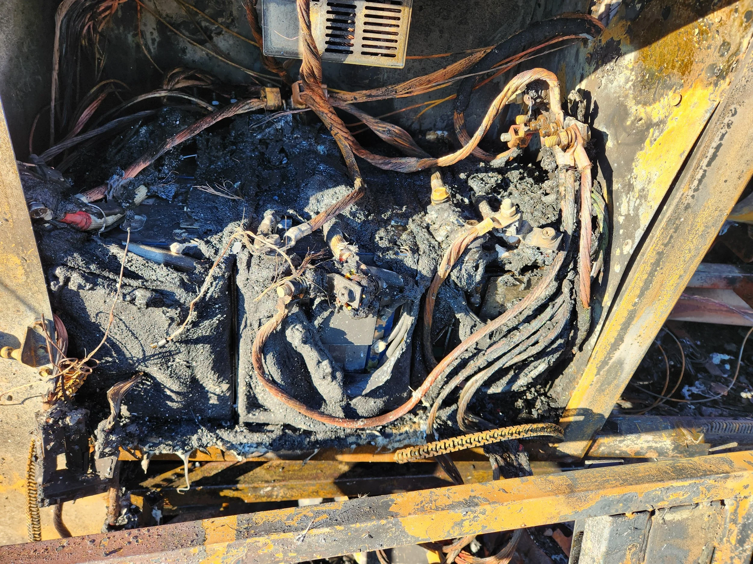
Figure 8: The remains of a battery compartment containing 4/0 cable and MRBF fuses. From a motorhome in Quartzsite, AZ.
All of this begs the question, should we really be connecting batteries in parallel just to power high-current loads like an AC unit or a heat pump? For myself, I draw the line at 2000W. If a mobile system needs 4/0 cable to function safely under high current, its time to increase the voltage with a series battery connection.
Limitations and Real-World Considerations:
Connecting batteries in series is not as practical as one might think. In theory, you’d just connect the positive of one to the negative of the other, and the remaining two terminals will have twice the voltage across them. But the big downside has to do with what’s inside of the battery.
A battery is just a series/parallel combination of smaller ‘batteries’ that we call cells. Each cell has a certain voltage and capacity, and these cells are combined inside of the battery case to create something like a 12V 100Ah LFP battery. Each cell has its own imperfections and internal resistance, which would cause the battery to deteriorate prematurely. It’s similar to what we described about balancing current sharing amongst a parallel battery. But with series connections, the problem is only exacerbated.
Let’s say our battery has 4 cells of 3V each combined in series to make up our 12V total. If we apply 12V of charging voltage to the battery, that doesn’t mean each cell will see exactly 3V. Some of the cells might absorb more current, while others might absorb less current. The cells that absorb more current will cause a greater voltage drop, which means there is less voltage for the other cells. Let’s say one cell draws 3.2V. Then the other three must split 8.8V amongst themselves, which means they are getting less than 3V each (assuming they share it equally). But if this happens, then the one cell will charge faster than the others, leaving an internal imbalance inside the battery!
Enter the Battery Management System. The BMS constantly monitors the voltage of each individual cell within the battery, and is able to control how much current goes into each cell in the series. If one cell has slightly higher resistance, the BMS will still make sure that cell gets exactly the same charge as the other cells to balance the overall capacity of the battery.
But here’s the catch - the BMS cannot control cells externally-connected through a series battery connection. So if we connect two batteries in series, sure the BMS of the one will keep those cells balances as will the BMS of the other. But the two BMSs cannot see just where each battery sits in relation to one another. So while all the cells in each battery might sit at the same voltage, it could be that battery #1 took in more overall current than battery #2, and neither BMS can see or fix that!
Since this is internal to the batteries, it isn’t a problem that external wiring can solve. Rather, we have to be a bit more creative. One solution is to buy batteries whose BMSs can be connected externally to each other, so they can remain balanced even with an external series connection. But these aren’t common and increase the project price. Option number 2 similarly is to buy an external BMS, which adds significant complication and isn’t feasible for most DIY installers.
The third and best option is to buy batteries that are already at the voltage we need. Rather than buying two 12V batteries and putting them in series, just buy a single 24V battery and use parallel connections for extra capacity. Sure, this doesn’t really help us if we started with 12V batteries. And ultimately thats a choice the end-user should make. Would you rather connect them in series and just let them be a bit unbalanced, or would you rather sell the 12V batteries and buy a new 24V one that will do the job better? It’s mostly a matter of budget and feasibility.
Oh, and keep in mind. While doubling system voltage will cut ampacities in half, you need to ensure compatibility with everything else in your system. Your inverter will need to be swapped out to match the input voltage, you may need a buck converter to power those pesky 12V-only loads, and your MPPT will need to be set to 24V if it doesn’t automatically make the switch. But as a bonus, you can now put twice the number of solar panels under the same MPPT!
Solar Panel Connections Intro
Fundamentally, connecting solar panels in series or parallel is the same as with batteries. Parallel? Connect positives together and likewise for negatives. Series? Connect positive to negative and repeat until you have one set left of positive and negative. But because we aren’t dealing with complicated batteries, we have much more flexibility and unique limitations that help us determine which is right for our needs.
As you read through these last sections, consider the example in Figure 9 to see a real-world example of where connecting panels of different wattages yields different results depending on whether they are connected in series or in parallel.

Figure 9: Solar Panel Connection comparison
Solar Panel Parallel Connections
Connecting solar panels in parallel can offer a great level of flexibility, even more so than with batteries. Unlike with batteries, sometimes one of our panels might produce less or no current due to shadows. If we connected them in series, then all of the panels in that string would be limited by the shade covering only one panel. But in parallel, we can have better resilience to partial or complete shading! This is because in series, a shaded panel acts like an open circuit, preventing any current from flowing at all. But in parallel, the shade only opens the circuit for the shaded panel, whereas the others still have a path for current to flow.
When connecting panels in parallel, we have to use something called a branch connector. This is just an MC4 connector with two inputs and one output. We just need to make sure that the branch connector is capable of handling the total current provided by all of the solar panels.
Also, because we don’t care about balancing capacity anymore, we don’t have to maintain equal wire lengths or even balancing current. No, with solar, we don’t care if one panel produces 2A and the other produces 20A. We just care that we do it in such a way that we maximize the total power we squeeze out of the sun with our limited roof space.
RV roofs are typically covered in a bunch of junk. A/C units, vent fans, windows, pipe vents, and so much else. We often want to maximize how much solar we can fit in the gaps between this equipment, and sometimes that means using panels of different sizes. But is this possible? Can we connect a 100W solar panel and a 200W solar panel under the same array and send it to a single MPPT? The answer isn’t a straightforward yes or no, but there are rules of thumb we can apply to maximize not just surface area, but also solar power yield to ensure we get the best results even in shading conditions.
Limitations and Real-World Considerations:
Solar panels are not one-size-fits-all. Each solar panel has its own maximum power voltage (Vmp) and current(Imp) ratings, sometimes referred to as operating voltage and current. When we’re connecting nonidentical panels together, we need to pay close attention to these values, as it affects how the entire solar power system interacts and produces power.
We should familiarize ourselves with how a solar MPPT charge controller works, because it plays a big part in parallel connections. An MPPT looks at the power produced by solar panels, and adjusts the output voltage and current to maximize the amount of power the panels generate from the sun. The problem is, the MPPT can only monitor one voltage from the solar array.
When we connect panels of different wattages, those panels could have significantly different operating voltages. One might produce 18V, while the other produces 24V. The MPPT will see both voltages, but it will have to pick one - typically the lower one. This means the 24V panel will only produce as much power as it can at 18V, leaving those extra 6V on the table as lost power. The actual physics is a little more complicated, but the concept remains. When we connect solar panels in parallel, a big voltage difference will result in lost power.
So how do we fix this? Well, there’s a few clever options. The first is to use two separate MPPTs, one for each panel voltage. This offers greater control and maximized the output of each panel. However this can be expensive, space-wasting, and impractical for small setups. The second and better option is to pick solar panels that have nearly identical operating voltages, + / - one volt.
Let’s use my setup for an example. I have two 175W solar panels permanently mounted flat on my roof. They each have an operating voltage of 18V. I wanted to have another portable solar panel to connect to my system to supplement charge when the clouds were out. I could have bought a 200W panel and wired in another MPPT, but that would have wasted space.
Instead, I recognized that my 30A MPPT was being underutilized and had extra capacity for a third panel. So instead, I used a 3-way solar branch connector and found a 120W portable panel with a max-power voltage of 17V. It was close enough in voltage that I could connect it through the branch connector (and 25ft of solar wire) to supplement power without compromising the output of my existing 350W array.
If I was parked under shade, I could plug that portable panel in parallel to my other panels and stick it out in the sun, and still get some power while camped in the forest. Or, I could park in a sunny area after a storm and get extra charging current to replenish my batteries, without compromising much power from my 350W panels. Its small, compact, plug-and-play, and offers me huge flexibility in suboptimal conditions! This is why parallel connections for solar panels can be so powerful.
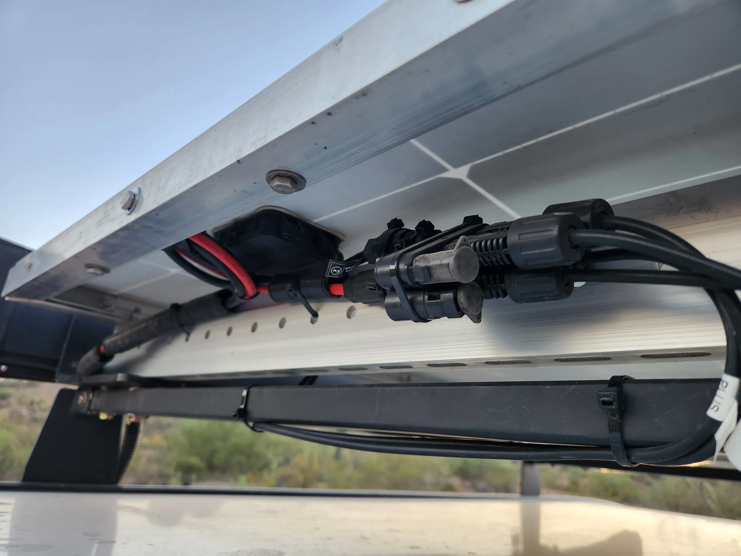
Figure 10: Solar panel parallel branch connector on my rig. Notice how the two 175W panels are permanently connected to the branch connector, with removable caps offering a parallel connection point for my 120W panel with a 25ft extension cord.
Solar Panel Series Connection
Often times on RVs, we see solar panels connected in series more than in parallel. When solar panels are connected in series, we call them a solar string. When a string is then connected in parallel to another, we call it a solar array. There are real benefits to strings, especially on larger motorhomes and campers where wire size matters more. The benefit is of course that panels in series generate higher voltages with less current. However, we have to plan carefully.
Most MPPTs can only handle 100V, with a few models that can go up to 150V or even 250V. If we’re working with 30V solar panels, we can only connect 3 in series for a 100V MPPT, or 5 for a 150V MPPT. But we have to make sure we’re looking at the open-circuit voltage for this scenario, because that’s the voltage the MPPT will see when it cuts off charging to some full batteries in direct sunlight. If the open-circuit voltage exceeds the MPPT rating, a fire could start.
A downside to connecting panels in series is poor shading performance. If one panel gets limited or completely shut off by a passing cloud or tree shading, then every panel in that series will experience the same bottleneck. Having something like Renogy’s shadowflux panels can significantly help bypass this issue with its better shading performance.
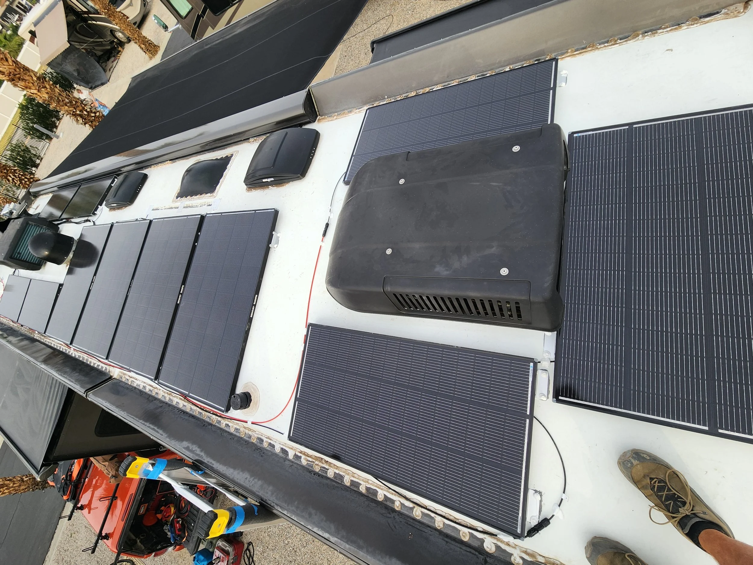
Figure 11: A 1760W solar array consisting of 1 string of 4x 200W Renogy Shadowflux panels, and 2 strings of 4x 120W Shadowflux panels. The 2× 480W strings were tied in parallel for a total of 960W feeding into one MPPT, and 800W feeding into the other.
What if we want to connect some panels in series, but they aren’t identical? For parallel connections, we made sure to match the voltage rating. So in series, we want to match the current rating. You can think of this like a kinked hose. If a certain part of the hose is kinked, then the whole line will only send out as much water as can pass through the kink. Its the same thing with solar panels - they can only send as much current as the weakest link in the chain. So by keeping the current ratings as close as possible, regardless of the voltage or wattage of those panels, we can successfully connect panels of different wattages in series with minimal losses.
Conclusion
That wraps up our discussion on series and parallel connections for RV solar power systems. There are many nuances that affect how we can optimize our system in the real world. But overall, the connections are fairly straightforward. I hope this article has better prepared you for planning out your own system!