
Van-Life Electrical Revamp - Pt. 2
Sometimes a job just isn’t about the money. Sometimes its about helping a friend to have a safe and effective system, when what they were given before was a disaster waiting to happen. That was the case for this client, who had first found me through my free solar workshops in Quartzsite. She was an enthusiastic learner, and a like-minded sovereignty seeker. She knew her system wasn’t providing enough charge, but getting more solar just wasn’t gonna work. Instead, she needed a DC-DC charger to help supplement her solar power when the weather got bad. We agreed to do the install with a DIY mentorship approach, showing her how to upgrade and maintain the system for herself in real time.
Safety - It’s Never an Option
We had spent some time looking over her system before the installation date, so the tight workspace and inadequate wiring wasn’t a complete surprise. But what did shake me was the complete disregard for safety that the last guy had for her van and electricity. While we disassembled the existing setup to create a sort of blank slate, we made several alarming discoveries. For one, some of the 1/0 copper lugs weren’t even crimped at all! Despite having heat shrink, I was able to pull the lugs off some of the wires with my bare hands. It’s a miracle she didn’t push her inverter very hard, because that was a disaster waiting to happen.
Additionally, because of how it was connected, some of her wiring actually got too hot and overheated with discoloration visible. This is because the last guy sent 1/0 cable from the inverter negative to chassis ground, and then 2 AWG from that same ground node to the battery negative. That 2AWG run was undersized to carry the full inverter current, so it got crispy. This wasn’t actually visible until we tore it apart and I ripped of the insulation to reveal the discolored copper. If the last guy had just sent the 1/0 directly to the battery negative terminal, this could have been completely avoided.
Last but not least, the one ANL fuse she had was pretty oversized. This 300A ANL fuse was the only thing between her inverter and the batteries, and while it may have protected her from a short circuit, it certainly failed to do anything against overload situations. We downsized to a 200A protection device to follow the NEC’s fusing guideline of 125% of the max circuit ampacity. This prevents nuisance tripping, maximizes overload protection, and guarantees fast action in the event of a true short.
Teaching and Wiring
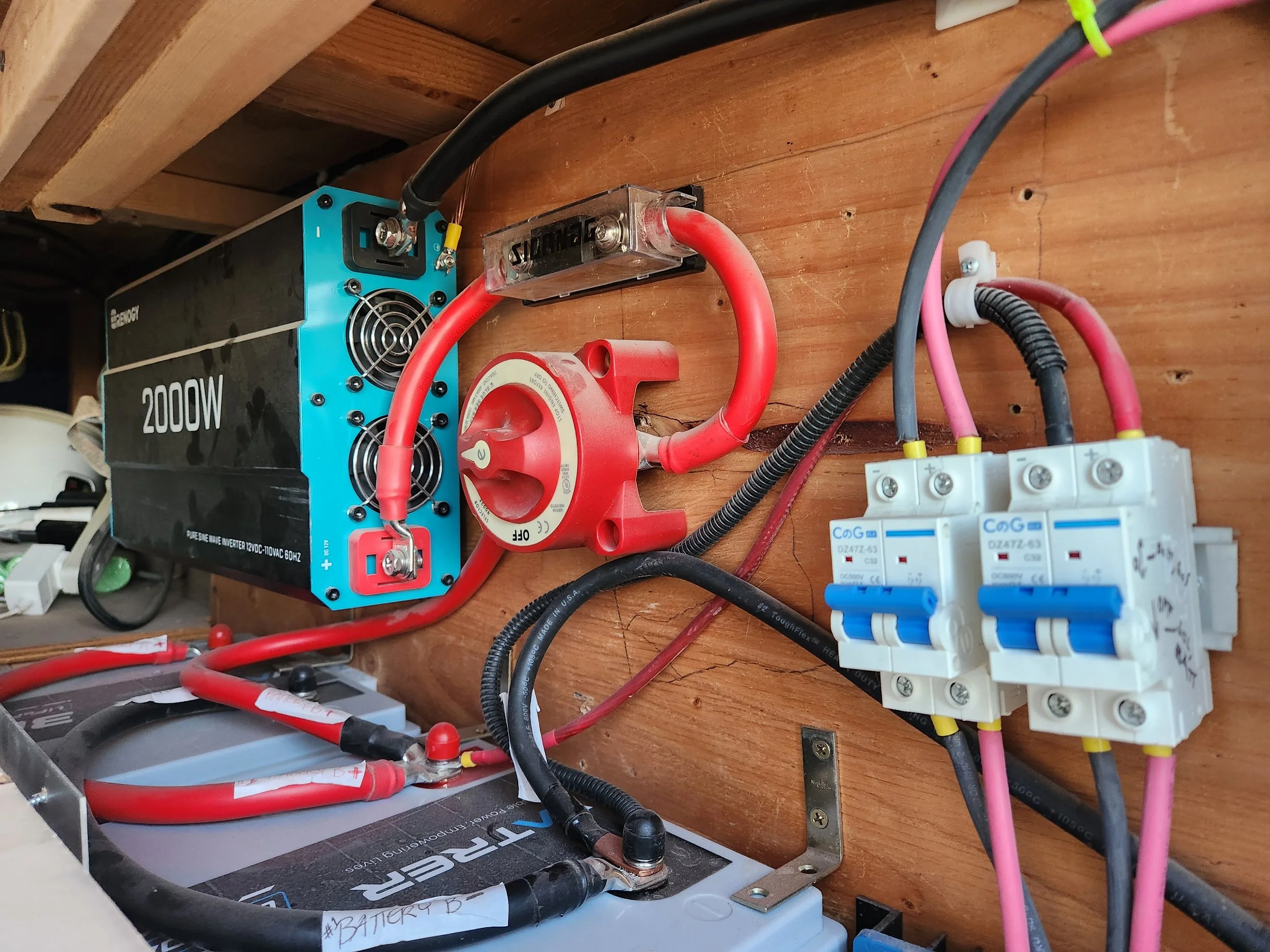
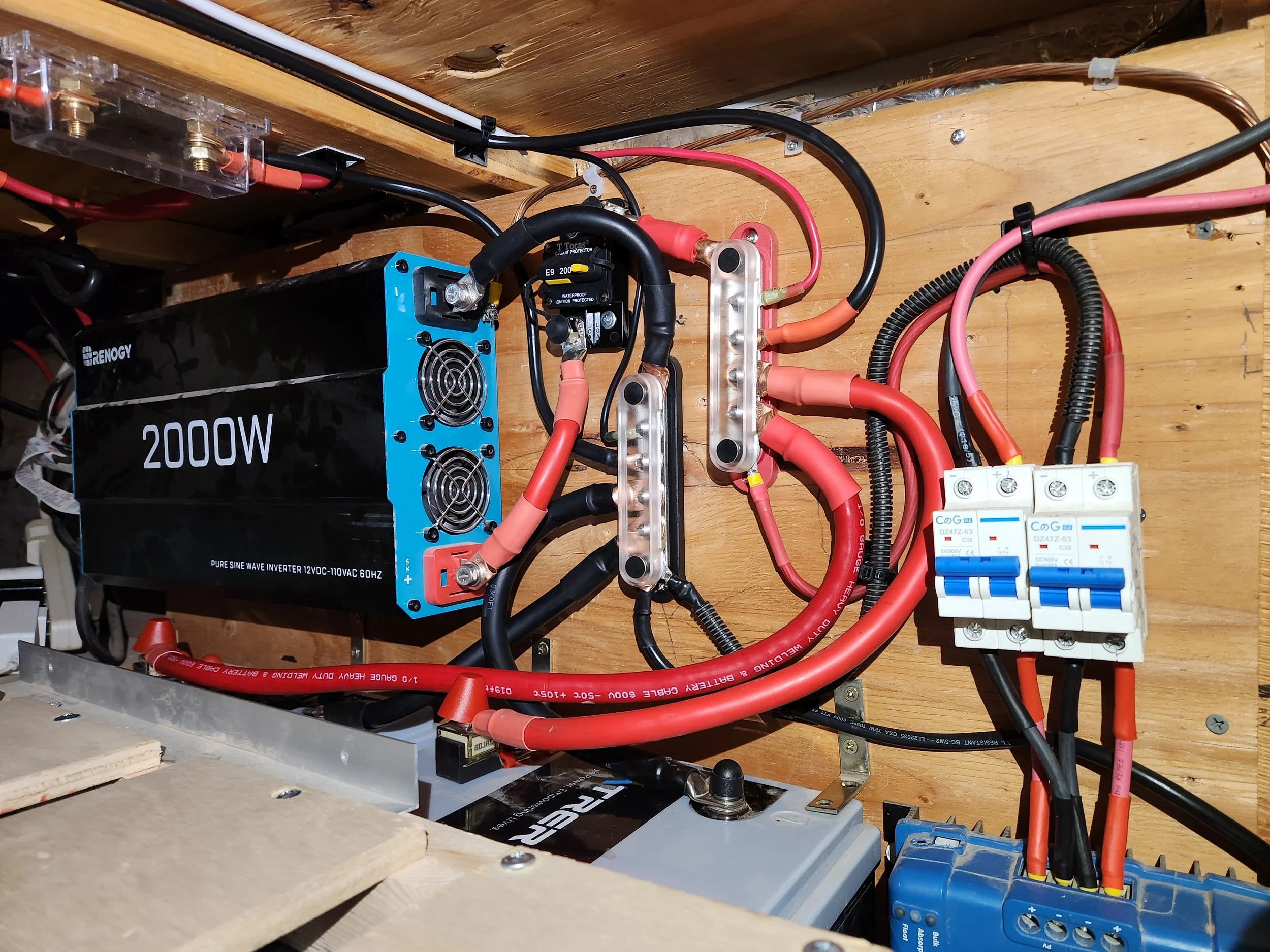
I always tell myself that if I could, I would redo everything from scratch for maximum cleanliness. The truth is that this is rarely feasible given constraints of time and budget. Nevertheless, I do the best with the resources given to me, and this job certainly ended a whole lot cleaner than it started. Every wire was re-crimped, any good quality wire was reused, and extra protection was added for maximum safety.
We started with the solar panels and MPPT, where I showed this client how to recrimp smaller wires and plan out the wiring to be neater than before. We used bus bars to consolidate every connection for neatness and ease of maintenance. We replaced the 300A fuse with a 200A resettable circuit breaker so she wouldn’t have to keep replacing fuses if she overloaded the inverter. We also added Marine-Rated Battery Fuses (MRBF) to each battery along with separate wiring to ensure equal sharing of current. I coached her through the wiring where she was comfortable, and stepped in for more critical connections like the battery terminals.
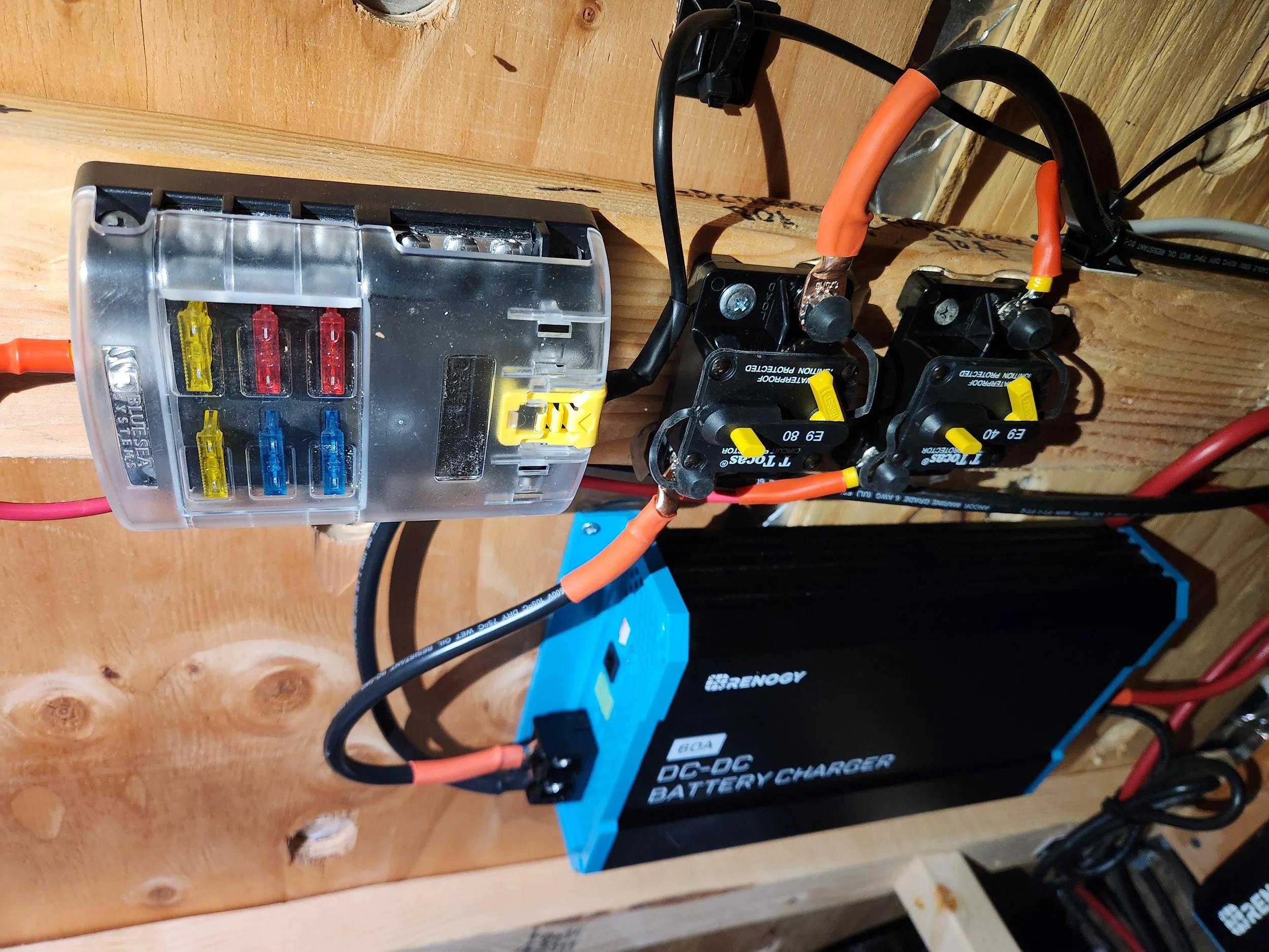
Installing The DC-DC Charger
A system rewire wasn’t even supposed to be the main part of this project. Our primary focus was on adding a 60A dc-dc charger to support her batteries when solar was underperforming. We ran the wiring from her starter battery all the way inside to the charger, and then to the bus bars through some fuses. A fuse on the starter side provided adequate fault protection, while a circuit breaker on the Lithium side gave the option of disconnecting the charger for maintenance. We even added a switch on the control line so she could shut the charger off while driving. This would be critical in extreme desert temperatures. With the charger installed, she was now prepared for the storms ahead.
#LessonsLearned
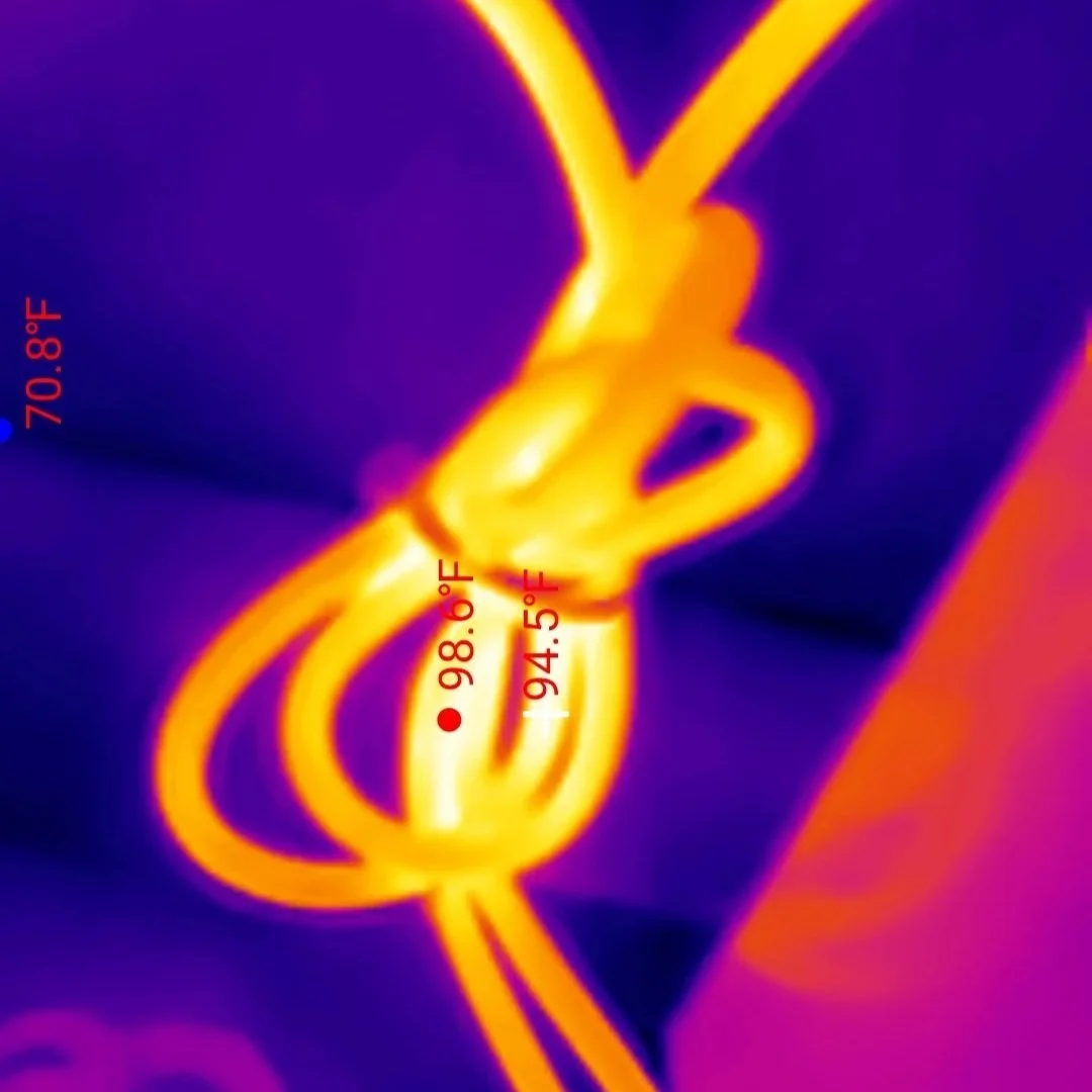
We did learn a valuable lesson with this install. I had used 6AWG wire between the starter and the charger, which normally can handle up to about 70A of current. However, we were already working in a fairly confined space, and she normally packed it tight with storage boxes and other cargo.
Measurements with the thermal camera revealed that this wire reached 100F while the charger was running, which would not be ideal given the storage and expected summer heat. While this may have worked in a more ventilated area, we should have upsized to 4AWG wire for better heat performance.
However, we settled with the option of plugging in a control wire to the charger to limit output current to 30A instead of 60A. That way, she’d still get a good amount of charge, and later on we could swap out the 6AWG wire with 4AWG when the timing worked better for us both. She needed to get to Mexico, and I to Flagstaff and beyond. This was the best compromise for both of us, it gave us peace of mind, and it’s a lesson that I’ve learned and will take with me to future jobs.
#LessonsLearned - Because we know the importance of being transparent with all our clients